
Your Source for Trays!

What Are the Top Types of TPS Sensors?

A throttle position sensor (TPS) measures how far the throttle plate opens and sends that information to the engine control unit. The signal helps manage fuel delivery, ignition timing, and acceleration response. Tps Sensors may look small, but their readings can affect how smoothly an engine idles or responds when the driver presses the pedal. A quick, steady signal matters.

The most familiar type uses a potentiometer, with a moving contact tracing a resistive track as the throttle shaft turns. It is straightforward and widely used, though track wear can create inconsistent readings. Hall-effect sensors detect changes in a magnetic field without relying on a sliding electrical contact. Magnetoresistive designs also read magnetic changes and may offer precise, contactless operation. Design details vary by vehicle. That matters.

This overview compares these common sensor types, explains how each works, and considers practical strengths and limitations. It also distinguishes sensor technology from features such as dual signal tracks, which can improve plausibility checks but do not define a separate sensing principle. A vehicle’s service information remains the best source for identifying its exact TPS design and test procedure. Similar symptoms can have different causes, so a rough idle alone does not prove the sensor has failed. Real diagnosis takes context.
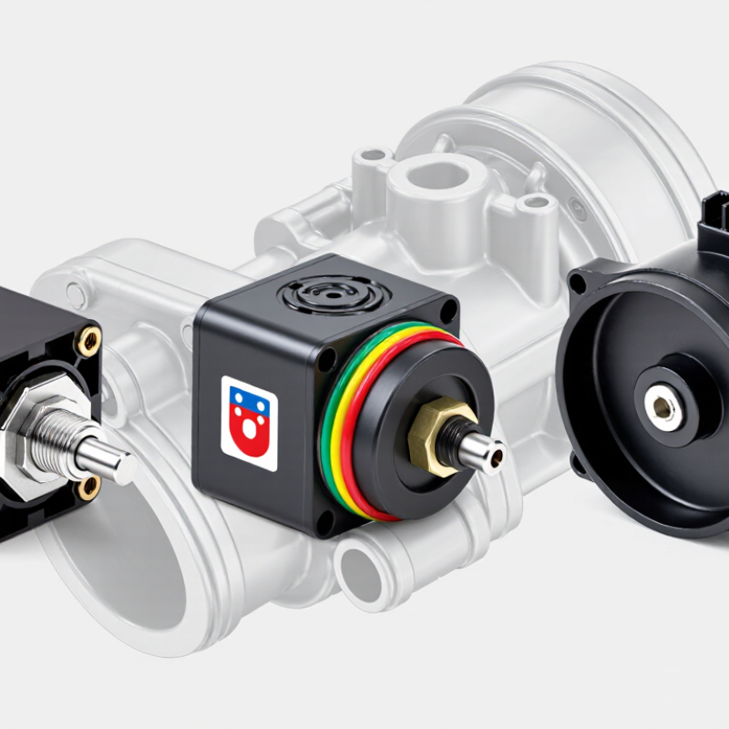
What Are the Top Types of TPS Sensors?

How Throttle Position Sensors Measure Throttle Movement

Throttle position sensors (TPS) track the angle of the throttle plate as it opens and closes. The sensor connects to the throttle shaft, so shaft rotation changes its electrical output. The engine control unit reads that signal to estimate airflow demand and adjust fuel delivery and ignition timing. Small movements matter. A slight press on the pedal can produce a changing signal before the plate looks much wider.

Common designs include potentiometric sensors and non-contact sensors, such as Hall-effect types. A potentiometric sensor uses a moving contact across a resistive track; its output voltage changes with throttle angle. Non-contact designs detect a changing magnetic field instead, avoiding direct contact with the sensing element. Many systems provide two signal tracks for cross-checking. Their readings should follow a predictable relationship, though exact patterns vary by vehicle. A worn track may create brief signal drops, sometimes felt as hesitation. Diagnosis still needs care: wiring faults can mimic sensor problems.

Tips: With the engine off, inspect the connector for loose pins or corrosion. Use a suitable scan tool to watch throttle-angle data while moving the pedal slowly. Look for smooth changes, not sudden jumps. Do not assume every reading difference means a failed TPS; specifications differ, and I’d verify the service data before replacing parts.

Potentiometer-Based Throttle Position Sensors

Potentiometer-Based Throttle Position Sensors

A potentiometer-based throttle position sensor tracks the throttle plate through a small rotating electrical contact. As the plate opens, the contact moves across a resistive track, changing the output voltage. The engine control unit uses that signal to estimate throttle angle and adjust fueling and ignition. Simple, but not foolproof. Wear or contamination can create brief signal dropouts, often felt as hesitation during gentle acceleration.

SAE J1979-DA defines the generic OBD-II Throttle Position PID (01 11) using the calculation A × 100 / 255, reporting a value from 0 to 100 percent. This standard helps technicians compare scan-tool readings, but it does not mean every sensor has the same voltage range or calibration. In practice, technicians check the signal while slowly opening the throttle and look for a smooth rise without sudden jumps. A single reading can miss an intermittent fault.

Tips: Check the wiring connector and ground before replacing the sensor. Watch live data during a slow throttle sweep; a brief drop matters. If readings seem inconsistent, verify them against the vehicle’s service specifications.

Hall Effect Throttle Position Sensors

What Are the Top Types of TPS Sensors?

Hall effect throttle position sensors deserve close attention in modern engine systems. Compared with resistive sensors, they measure throttle angle without a rubbing contact. A small magnet rotates near a sensing element. The changing magnetic field alters the output voltage. The engine control unit reads this signal to adjust fuel and throttle response. In workshop testing, a stable voltage curve usually indicates healthy operation. That matters during gentle acceleration and sudden pedal movement. Still, “contactless” does not mean failure-proof. Heat, wiring damage, poor alignment, and moisture can cause inaccurate readings.

Tips: Check the reference voltage, ground, and signal wire before replacing the sensor. Use a back-probe method and avoid forcing sharp probes into connectors. Move the throttle slowly while watching the signal with a suitable meter or scan tool. The voltage should change smoothly, without sudden drops or spikes. Inspect the connector for loose terminals. A weak ground can mimic a sensor fault. This simple step is often skipped.

Hall effect TPS units commonly use dual signal tracks for safety monitoring. The two outputs may follow different voltage ranges. If they disagree, the control system can store a fault or limit throttle operation. Correct installation requires proper alignment and calibration when specified. I have seen new sensors perform poorly after rushed fitting. That lesson is easy to overlook. A sensor may pass a static test yet fail during vibration. Good diagnosis combines live data, wiring checks, and mechanical inspection.

What Are the Top Types of TPS Sensors? - Hall Effect Throttle Position Sensors
Hall Effect TPS Type Operating Principle Typical Output Channel Configuration Typical Supply Voltage Key Advantages Common Use
Single-Channel Linear Hall TPS A magnet rotates with the throttle shaft, and the Hall element measures the resulting change in magnetic field without physical contact. Ratiometric analog voltage that changes progressively with throttle angle. The exact voltage range is application-specific. One sensing channel Commonly 5 V; some designs operate from lower regulated supply voltages. Non-contact operation, low mechanical wear, smooth position feedback, and simple electronic integration. Basic electronic throttle systems, small engines, generators, and industrial control equipment.
Dual-Channel Redundant Hall TPS Two Hall sensing channels monitor the same throttle movement through separate signal paths. Two position signals, often with different slopes, offsets, or voltage ranges to support plausibility monitoring. Two independent channels Commonly 5 V, subject to the vehicle or controller design. Improved fault detection through signal comparison and better suitability for safety-related throttle control. Automotive electronic throttle controls and systems requiring redundant position feedback.
Dual-Output Inverse-Slope Hall TPS Two Hall channels produce position signals that move in different directions or follow different transfer characteristics as the throttle opens. One output generally rises while the other falls, or the two outputs use different calibrated slopes. Two correlated channels Typically 5 V in many automotive applications. Provides an easily monitored relationship between channels and helps identify wiring, sensor, or mechanical faults. Safety-monitored throttle bodies and other applications using controller-based plausibility checks.
Programmable Hall TPS A Hall sensing element and signal-conditioning circuit convert magnetic position into a calibrated output profile. Configurable analog, PWM, or other digital-compatible output, depending on the device design. Single or dual channel Often designed for a regulated supply in the approximate 3.3–5 V range. Supports customized angle ranges, output curves, zero positions, and end-of-travel settings. Specialized throttle assemblies, industrial machinery, robotics, and low-volume equipment.
Rotary Hall Position TPS A rotary magnet and Hall sensing circuit measure shaft rotation over a defined angular range. Usually an analog position signal; some versions provide PWM or another digital position format. Single or redundant channel Commonly 5 V, with the permitted range determined by the electronics. Compact construction, sealed non-contact sensing, and suitability for applications exposed to vibration or contamination. Throttle shafts, accelerator mechanisms, valve actuators, and other rotary position applications.
Values shown are typical design characteristics rather than universal specifications. Exact voltage ranges, angular travel, temperature limits, accuracy, and diagnostic requirements depend on the specific application and calibration.

Inductive and Magnetoresistive TPS Designs

Throttle position sensors (TPS) measure the angle of a throttle plate and send that information to engine controls. Inductive and magnetoresistive designs do this without a sliding electrical contact. That can reduce wear where dust, vibration, or repeated movement challenge older contact-based designs. Small details matter.

An inductive TPS uses energized coils and a moving conductive target. As the throttle shaft turns, the target changes the magnetic coupling between the coils. The sensor electronics interpret that change as position. The method can work reliably without the target touching the sensing elements, but coil layout and nearby metal can affect performance. A technician may need to check the wiring and signal with suitable diagnostic equipment, not just inspect the connector.

A magnetoresistive TPS instead detects changes in electrical resistance caused by a magnetic field. A small magnet moves with the throttle shaft, while sensing elements track its changing orientation or field strength. The resulting signal can be smooth and precise, though magnet placement and temperature compensation matter. Not every design behaves alike. In real service, “inductive” or “magnetoresistive” alone does not reveal signal format, fault strategy, or calibration needs; the sensor’s specifications and measured output still deserve careful attention.

How to Compare TPS Types by Accuracy and Durability

Throttle position sensors (TPS) commonly use resistive contact, Hall-effect, or magnetoresistive designs.

A resistive sensor moves a wiper across a track as the throttle plate turns. It can provide smooth readings when new, but repeated movement may wear the track.

Hall-effect sensors detect a changing magnetic field without physical contact, reducing friction and wear. Magnetoresistive designs also read magnetic changes and can offer stable signals in compact assemblies.

Accuracy depends on more than sensor type. A well-calibrated resistive unit may outperform a poorly installed non-contact sensor.

Check signal smoothness across the throttle’s full travel, not just at idle. A diagnostic scan tool can reveal sudden voltage drops or inconsistent readings.

Durability depends on heat, vibration, moisture protection, connector quality, and operating cycles. Non-contact sensors often have an advantage in high-cycle use, though electrical faults can still affect them. Real conditions matter.

Tips:

Compare the stated operating range and environmental rating.

Inspect connectors and wiring before blaming the sensor.

Small voltage fluctuations may come from installation or corrosion, not a failing component.

No type wins every test; vehicle specifications should guide the choice.

Article Source: